Configuring an ATMEGA328P to Replace an Arduino Uno
Bare minimal setup of an Arduino Uno
Rationale
This project was part of an even bigger project. But essentially, we wanted to use the ATMEGA328P instead of the Arduino Uno. For those who do not know the Arduino Uno uses the ATMEGA328P microcontroller. So we wanted to just use the microcontroller as is for a few reasons - cheaper and more power efficient.
This configuration allows programming of the ATMEGA328P using the Arduino IDE with almost no restrictions
Requirements
- Arduino Uno with existing ATMEGA328P
- ATMEGA328P
- Wires (Either use jumper wires or solid core hookup wires which require wire strippers, pliers and cutters)
- Breadboard
- Small flathead screwdriver
- Multimeter
- 0.1 uF ceramic capacitors (Labelled 104 usually)
- 10k resistor
- LEDs (for debugging if you want)
- Arduino IDE
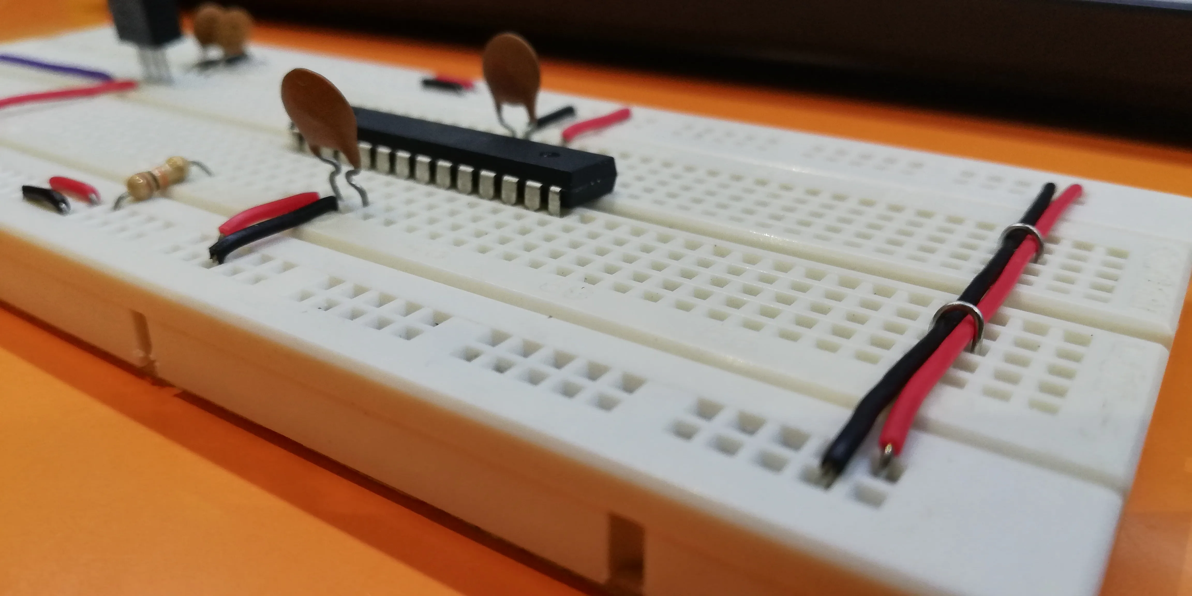
Breadboard Setup
First, let’s connect the ATMEGA to our breadboard. Wire the breadboard as per below.

Burn the Bootloader
Most ATMEGA328Ps do not already have the bootloader installed so we need to burn the bootloader on to the ATMEGA328P.
Below is the pinout for the ATMEGA328P. Note that pin 1 is denoted by a small dot indentation on your ATMEGA328P

Connect the Arduino Uno to the breadboard as per below. In other words, connect the pins 11-13 on the Uno to the corresponding Arduino pins on the ATMEGA328P, followed by a connection between pin 10 on the Uno and pin 1 on the ATMEGA328P.
| Arduino Uno Pin | ATMEGA328P Pin |
|---|---|
| D9 | 9 (Uses internal 8MHz clock) |
| D10 | 1 (Reset) |
| D11 | 17 |
| D12 | 18 |
| D13 | 19 |
| 5V and GND | Refer Below |
You can choose to use the Uno’s 5V and GND to power the ATMEGA328P or use an external power source with a 5V regulator. Just connect the 5V wire to the red circle and GND to the black circle as shown below.

A full setup of my messy wiring is here.

Upload the ArduinoISP code to your Uno, setting the usual Board and Programmer. From File > Preferences, add the following Boards Manager URL:
https://mcudude.github.io/MiniCore/package_MCUdude_MiniCore_index.json
If you already have other URLs, append it separated by a comma. Restart your Arduino IDE. Open Tools > Board > Boards Manager and search for the MiniCore. Install the latest version, then restart your IDE. Select the ATMEGA328 board under Tools > Board. You are now presented with many settings. You can ignore most of them for now. Choose the clock you intend to use. If you do not have an external crystal oscillator, just select Internal 8MHz. Set the other settings as follows
| Tools | Setting |
|---|---|
| Board | ATmega328 |
| Clock | Internal 8MHz (If using internal clock) |
| Variant | Depends on your MCU (ATMEGA328____) |
| Programmer | Arduino as ISP |
Now go to Tools > Burn Bootloader. It should look as if code is being uploaded, followed by a message saying “Done Burning Bootloader”.
This completes the burning of the bootloader. You may disconnect the wires stated in this section.
Uploading Code
We can now use the Arduino Uno simply for debugging and uploading purposes. However, to ensure the code is uploaded into the ATMEGA328P instead of the Uno, we need to remove the ATMEGA328P inside the Uno. Please make sure that you are using a similar model as mine in which you can remove it (Refer to Arduino Uno image below). If not, I strongly suggest you invest in an FTDI cable. I also highly DO NOT recommend plugging the ATMEGA328P in and out of the Uno.

The best way to remove it is exceedingly disgusting. Use a flathead screwdriver as a lever and slowly pry out the ATMEGA328P. Do it on both sides bit by bit, taking care not to bend the pins. Once one side is entirely out, hold on to that side using your hand and use the screwdriver to pull out the remaining pins. Clearly, no one likes to do this, so if you’re gonna do it multiple times, use a ZIF.
Connect the Arduino Uno to the breadboard as per below.
| Arduino Uno Pin | ATMEGA328P Pin |
|---|---|
| RESET | 1 |
| RX (D0) | 2 |
| TX (D1) | 3 |
| 5V and GND | Same as Bootloader Burning |
Set the following settings in your Arduino IDE:
| Tools | Setting |
|---|---|
| Board | ATmega328 |
| Clock | Internal 8MHz (If using internal clock) |
| Variant | Depends on your MCU (ATMEGA328____) |
| Programmer | Arduino as ISP |
Now you can test a blink code by uploading the following code:
void setup() {
  pinMode(8,OUTPUT);
}

void loop() {
  digitalWrite(8,HIGH);
  delay(1000);
  digitalWrite(8,LOW);
  delay(1000);
}
You can test it is working by connecting the red pin of the multimeter to the pin 14 (last pin on the same row as pin 1) and the black pin of the multimeter to GND. Watch as the voltage increases and decreases. You may also add an LED if you would like, connecting it to the same pin and GND.
To confirm it is definitely working, you can change the delays.
Conclusion
So that is how we can create a more minimal setup to replace the Arduino Uno. This saves power and costs if you intend to have multiple setups. In our use case, we needed roughly 30 microcontrollers to work together, so spending $20 on a single Uno vs a couple of dollars on each ATMEGA328P definitely saved us a lot of our budget.
I’ve also compiled all my references in case you wanted to read up a bit more, or do things a little differently. Nick Gammon’s guide was my primary source of information though the instructions tend to be a bit long due to the large coverage of his article. I’ve also chosen to use MCUdude’s MiniCore instead due to its high configurability.
Resources
http://www.gammon.com.au/breadboard
https://github.com/MCUdude/MiniCore
https://www.youtube.com/watch?v=Sww1mek5rHU
https://www.youtube.com/watch?v=dpgcBsl9D4k